Test integrated circuit HOW TO TEST ICs CHIPS by Multimeter

HOW   TO  TEST   ICs    CHIPS     by     Multimeter  


BASIC    ICs    TESTING  ,  test integrated circuit

electronic  components  testing
                                 How  to   test  integrated   circuit    by  Multimeter


ICs   is  a    circuit and  there are  many small  electronic components  inside it.   ICs has many type , style ,  including its complexity.    On   this article  I will refer to standard  ICs   that  we always find it   at common circuit and I will use standard ICs  for example testing.    For special purpose ICs you can check  with  ICs  maker  how to check and test  it  ,  test guide and specification data can  get these from datasheet ;   type ICs part number on google  search  by   this  you will find datasheet as PDF file.  On datasheet  will  present electrical characteristic  , test graph for designer  and  checking , pin  arrangement  function , sizing  for installation   and   safety  advice.


They    are   2  basic method  to check   ICs.
1)  On circuit  testing .    If  you have oscilloscope  and know  how  circuit is working   such as input , output ,condition  to  on  and off , type of  signal  ; then you can consider it  as block diagram  and section to test.
At the ICs you will check  input  voltage  is present  or  not , output occur  after the input switch on/off or not.     Including   Vcc  of  ICs  should be value  as   its rated voltage.

2.    VCC   and   ground   terminal   resistance   checking.    As    inside  the  ICs  there is  some circuit  , it need voltage to supply and the circuit inside must not  " short circuit "  and  " open circuit"  these is the basic condition for good ICs , we will apply this to check ICs   and   describe below.

Take  ICs part number  that   marked on its body to find  pinning function  on datasheet ,  find  where  is VCC and ground pin  locate. Some ICs has many VCC and ground pin ,   you  to check  all  VCC  pinning  and  it  must be good condition for all VCC.     I will use ICs part number HD74LS00P  for example testing.   Set  multimeter  to resistor  test function then   connect   as  shown  on   photo , measure ,   and  read  resistance value.


HD74LS00P  pining arrangement   ( different  ICs  part number  has different VCC pin  allocation )
The notch  and circle on ICs   mean  pin no.  1  start  from that point.


Pin no.  1  start   at  the dot and notch.
                                                     TEST ICs CHIPS with Multimeter


                VCC and GND testing , The  first  measurement   and   test   leads    connection


electronic  components  testing
The    first   measured  resistance value is  high ( for good ICs)


VCC and GND testing , the  second  measurement  and  test leads   connection.

TEST   ICs   CHIPS
The  second  measured resistance value  is  lower  compare to  the first. ( for good ICs)


2.1 
Good  ICs .... measured  resistance value of  VCC and ground  testing ,  the first measurement  and  second measurement  , the first testing resistance value  is high and the second is low ( compare to the first ).  See  above  photo for   example.

2.2
Bad  ICs (leak)........both measured resistance  value   tend to the same value and very  high  resistance.

2.3
Bad  ICs (Short circuit) ....both  measured resistance value tend  to  very low resistance ( almost be  0  ohm )

2.4
Bad  ICs ( open  circuit) ... the display show  " OL"   for both    measurement.


Read    more   of    testing  ,   list    of    article   here .


HOW TO TEST ICs Chips VOLTAGE REGULATOR 78XX 79XX series 7805 7815 7815 test integrated circuit

HOW   TO   TEST   ICs   Chips   VOLTAGE   REGULATOR

IC   VOLTAGE    REGULATOR    TESTING   /   test  integrated   circuit  


test  integrated   circuit    TEST   VOLTAGE  REGULATOR
                                  

IC regulator   LM317T  7915CT   L7809CV
                                 IC  Regulator   LM317T   7915CT   and   L7809CV on  PCB


IC  Voltage  Regulator  part number  78XX  79XX series  are  popular ICs that  use  on  many power supply circuit.   Regulate voltage function  is  necessary  for every  electronic circuits so we always find these ICs   on  many circuits  ,  The  ICs  is  small and has  many package to choose.    The basic  package is  TO-220 and  TO-3  as  shown on   photo below.   78XX series is  for positive output   for part number  example   7805 =  5VDC    ,  7812 = 12VDC  ,  7815 =  15VDC etc.   79XX series is  for  negative  output  for  part number  example 7 905 = - 5VDC    ,  7912 =  -12VDC  ,  7915 =  -15VDC etc.   The part number has  L  at  the middle like 78L05  , 78L12 , 78L15 means  it  has  output  current    around 100mA   and  part number  has T at end  like  7805T , 7812T , 7815T

HOW TO TEST OPTOCOUPLER ICs CHIPS test integrated circuit

 OPTO   COUPLER   TESTING   

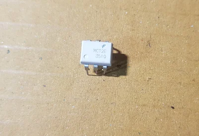
Optocoupler  is one   type of  ICs , It   isolates input  and output section  by using  optical technology  this  feature  increase safety of  circuit.  Optocoupler  has many   part number , different  part number has different output type so before checking it   has to  use part number to  research with datasheet and find input type and output type.   How to check  Optocoupler it depends  on  device type inside the ICs.   There   are  many package of  Optocoupler , briefly ,  through hole and  SMD.  For  through hole type such as  DIP-6  which  has 6 pin   DIP-4  which   has  4   pin  etc.


test  integrated   circuit    OPTOCOUPLER    ICs
Optocoupler   MCT2E  DIP-6   Package


I   will    use MCT2E   for example testing.  After researching with datasheet we know input is LED
terminal   number .  1   is  Anode and  terminal  number 2  is  cathode , this case ,  we  will check it by using  the same method  as   LED checking.   The dot on ICs body mean that the first pin start from that.   The   output  is  a   transistor pin number  6 is  Base terminal ,  pin number  5 is  Collector terminal and  pin number   4   is Emitter terminal , so  checking method  it  has the  same method  as  transistor  checking.


Step  to  test   Optocoupler.
1.  Input   Checking.

HOW TO TEST LED by digital and Analog multimeter test led with multimeter

  Test   LED   with   Digital  and  analog  multimeter 

Test  LED with multimeter
                                        Test  led  with  multimeter

LED    TESTING

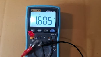
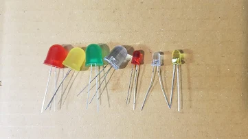
LED  is   a    kind  of  diode  and  it is a  basic electronic device on circuit so  it's good to know  how to check LED  good or bad.  The common size available on  the market is  3mm  5mm and  10mm Dia which is popular type  and other size and style  are  produced  too but it  use with some equipment.  . Before checking  LED , it  need  to know the most important information
1). Specification of  LED    2) Test  Function of multimeter    to check  LED.
After learning  these 2  points   then  we  can  move to  step  to LED checking.


Light emitting  Diode  LED
                                       LED  size  and  color

1). Specification of  LED.
Led   is  a  low current consumption  device.  Don't let too much current  flow through it when using  at circuit  it always  need  limiting current resistor to decrease the current.   Limiting resistor calculation will  be discussed  when make a circuit design.   Generally small led need current  around  10-25mA and  big led  around 20-50mA  so  when  check it  by analog multimeter  use the proper current range  to check it and don't hold the test  lead  for a long  minute   , we  will describe on the  next section.

Multimeter test bridge rectifier diode

HOW   TO   TEST   BRIDGE   RECTIFIER   DIODE   


HOW TO  TEST  BRIDGE  RECTIFIER  DIODE
                                          HOW TO  TEST  BRIDGE  RECTIFIER  DIODE


HOW  TO   TEST   BRIDGE   RECTIFIER   DIODE 


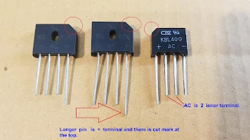
Full  bridge   rectifier  diode   consists   of   4   diode  inside the package.   It   is  a  common part of power supply.   Internal  wiring for  4  diodes  shown  as   below. Although   there are many package of   Full  bridge  rectifier   diode ,  it has the same internal wiring diagram  and   4  terminals  , namely  ;   +  ,   -   AC  and   AC.
The  +  terminal  has longer lead   than the others   and   there is cut  marking  at the corner .   The sip package AC and AC leads   located   at  the  inner.  KBPC package  indicate only  2  terminal name that   is   +   and  AC ,    the others  you have to  find  ...  -   terminal  is  diagonal  to the  +  terminal and  the rest  AC terminal   is  diagonal   to   the first   AC  terminal   too.


BRIDGE  RECTIFIER  DIODE
                                      Leads   arrangement   of    BRIDGE  RECTIFIER  DIODE

Multimeter test capacitor and how to test electronic components

 HOW   TO   TEST    CAPACITOR

CAPACITOR   TESTING.    This article  will  explain  both  capacitor testing  using  digital multimeter and  analog mulimeter.


Step  to  test  capacitor  with  digital  multimeter

1. Remove power  from circuit  by switching equipment   off  / unplug.  the capacitor under test must no voltage  present.
2. Discharge capacitor before testing , failture to do this will case damage to meter and electric shock.
Researching  how to discharge capacitor is essential too.
3. Don't touch metal tip of  test  leads  during testing.
4.  Insert black test lead to COM- jack  and  red test lead  to  VΩ  jack.
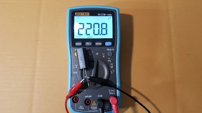
5.  Turn rotary switch  to  capacitor  range / capacitor test function.  The display will  present  capacitor symbol.
6. Connect   the   test  lead    to  capacitor   under test terminals.
7. The  display will   present   some   capacitor   value.
Good capacitor will show value as printed on its body ( the closest value is still good capacitor ).
Bad capacitor ( degrade ) show capacitance value much lower from it  original value.
Bad capacitor ( open ) will not show any  capacitance value.
Bad capacitor ( short ) will not show any  capacitance value or  show " OL"


Test   capacitor   HOW   TO   TEST    CAPACITOR


Step to test capacitor with  Analog  multimeter.
1. Remove power from circuit by switching equipment   off  / unplug.    The capacitor under test must no voltage   present.
2. Discharge capacitor before testing , failure to do this will cause damage to meter and electric shock.
3. Don't touch metal tip  of  test leads  during testing.
4.  Insert black test lead to COM- jack  and  red test lead to  P +  jack.
5.  Turn rotary switch to  resistance   range / resistance  test  Function.
Capacitance value around  10uF  use   Rx1K range.
Capacitance value around  47uF  use   Rx100 range.
Capacitor value around  470uF - 2200uF use  Rx10  range.
Capacitor value around  2200uF up  use  Rx1  range.
6. Test  2  time , connect test leads   to  capacitor terminals  and  switch  test leads and  do  testing  again.   The meter will  present  result as below.
Good capacitor  , the pointer will move forwarding   to 0  ohm side  then  move  backward  to ∞ .
Bad capacitor (open)  , the pointer does not   present   any   movement.
Bad capacitor (short )  , the pointer move forward  to 0 ohm side and keep position around 0 ohm.
Bad capacitor  ( leak ) , the pointer will move forward  to 0 ohm side  then  move  backward  to ∞ but  it does not reach  ∞  position. ( The pointer still  point at some resistance , not at  ∞  position  as  a  good capacitor ).


Test  multimeter    test Capacitor
                             Test  capacitor  with  Analog  multimeter  ,  220uF use  Rx100 range.


Read     more    of      testing   ,  list    of    article   here .


HOW TO TEST TRANSFORMER with Digital Multimeter and Analog Multimeter

 HOW  TO   TEST   TRANSFORMER     with    Multimeter

TRANSFORMER  TESTING    Transformer   consists  of   2 winding  ;   primary winding and secondary winding.   Transformer is  the important device on power supply circuit. It convert  high voltage to low voltage  and provide safety feature as  isolation between input and output ,  Isolation  between  high  AC voltage and  low AC voltage can  achieve   by transformer.  This article explain basic transformer testing.


Step to test transformer with Digital Multimeter.

1. Turn equipment  off ( unplug )  or    remove power source  from transformer under test.
2. Turn rotary switch  to  resistor  test  function.
3. Connect test leads  to  primary  winding.
Good transformer get  measured  resistance value.
Bad transformer  ( open winding )  meter display  " OL "
Bad transformer  ( short turns )  meter display   0 ohm  or  very much low  resistance.
4. Connect test leads  to  secondary  winding.
Good transformer get  measured  resistance value.
Bad transformer  ( open winding )  the  meter display " OL "
Bad transformer  ( short turns )  meter display very much low resistance.


Test   TRANSFORMER

                                 Test   primary   winding , display  resistance value.
                                  Bad transformer display " OL" (for open ).
Bad transformer display very much low resistance  (for short ).


HOW  TO  TEST  TRANSFORMER  with Digital Multimeter
Test   secondary    winding ,display resistance value.
Bad transformer display " OL" (for open ).
Bad transformer display very much low resistance  (for short ).


5. Test transformer core with primary winding.  ( Isolation testing)
Connect test leads   to transformer core  and  primary  winding.
Good  transformer  meter display " OL "
Bad transformer   meter  display some resistance (leak)
6. Test transformer core with secondary  winding. ( Isolation testing)
Connect test lead to transformer core  and  secondary  winding.
Good  transformer  meter display " OL "
Bad transformer  meter display some resistance (leak).

TRANSFORMER
Test transformer core with primary winding ( isolation testing).
Good transformer meter display "OL"
Bad transformer (leak) meter display some resistance value.


Test   TRANSFORMER
Test transformer core with  secondary  winding ( isolation testing).
Good transformer meter display "OL"
Bad transformer (leak) meter display some resistance value.


7.  Test isolation between  primary winding and secondary winding.
Connect test leads   to primary winding   and secondary winding.
Good  transformer  meter display  " OL ".
Bad   transformer (leak)   meter display some resistance.


TEST  TRANSFORMER
Test isolation between  primary winding and secondary winding.
Good transformer meter display "OL"
Bad transformer (leak) meter display some resistance value.


Step to test transformer with  Analog  Multimeter.
1. Turn equipment  off ( unplug )  or remove power source  from transformer under test.
2. Turn rotary switch to  resistor test function , Rx1 range.
3. Connect test leads  to  primary  winding.
Good transformer get  measured  resistance value.
Bad transformer  ( open winding )   the  pointer point at  " ∞  ".
Bad  transformer  ( short turns )  the pointer point at   0 ohm.
4. Connect test leads  to  secondary  winding.
Good transformer get  measured  resistance value.
Bad transformer  ( open winding )  the  pointer point at  " ∞  ".
Bad transformer  ( short turns )  the pointer point at   0 ohm.


Test   transformer
Test   primary  winding, use Rx1 range ,
 meter display some resistor for good transformer.


Test  TRANSFORMER
Test   secondary   winding, use Rx1 range ,
 meter display some resistor for good transformer.


5. Test transformer core with primary winding. ( Isolation testing).
Turn rotary switch  to   Rx10K range test function.
Connect test lead to transformer core  and primary winding.
Good  transformer  the pointer  point  at   " ∞  ".
Bad transformer  (leak)  the pointer show some resistance value.
6. Test transformer core with secondary  winding. ( Isolation testing).
Connect test lead to transformer core and  secondary  winding.
Good  transformer  the pointer point at   " ∞  ".
Bad transformer (leak) ,  the pointer  point  at  some  resistance value on scale.


TRANSFORMER
Test transformer core with primary winding ( Isolation testing ).
Good transformer  ,  the pointer must point at " ∞  ".


TEST   TRANSFORMER

Test transformer core with secondary  winding ( Isolation testing ).
Good transformer , the pointer must point at  " ∞  ".


7.  Test isolation between  primary winding and secondary winding.
Connect test leads  to primary winding  and  secondary  winding.
Good  transformer  ,  the pointer point at   " ∞  ".
Bad transformer   ,   the pointer  point  at  some  resistance value on scale.


How   to   check  electronic   device

HOW TO TEST SWITCH Toggle switch Rocker switch Limit Switch


Test    SWITCH    Toggle  switch   Rocker  switch   Limit  Switch

All   kind  of switch   has mechanical  contacts.  The most basic of contacts   is   NC  type contact ( Normally Close )  and   NO   type contact ( Normally  open ).  Some switch has only 1 NC contact  , some switch  has  only  1  NO contact  , and some model consist  of  many  contacts ;  NO  NC Common terminals.      The circuit diagram of  switch  has   printed  on  its  body.    How  to  check  switch   it depends on contact  type of  witch.


NC type contact ( Normally Close )  , Terminal 1 and 2 is connected


NO type contact ( Normally  open )  Terminal 1 and 2 is  not  connected


Basic  output contact form  consists   of   NC  and  NO contact


Step to check  switch


1. Turn   rotary  switch to  continuity test function  of   digital multimeter.
2  Connect  test  leads  to  the  NC contact  of  switch.   The  meter  will  beep  if  it is a  good NC contact.   Bad  NC contact  , the meter does  not beep.   After that change  switch  position by pressing to  ON and  OFF.   The good contacts  will change status  from ON  to OFF or  OFF to ON.
3.  Connect  the  test leads to  the  NO  contact.   The  meter  will  not  beep  if  it is  a good NO contact.   Bad  NO  contact  , the meter will  beep ( short circuit).
After that change switch position by pressing to  ON and  OFF.   The good contact will change status from OFF  to ON  and ON  to OFF.   These changing of contact  represent results  on  multimeter display.
4. Test   every  NO   and NC contact set.  If there is only  1 contact is bad , the  switch  is  not  good.
then find the replacement.

Test    SWITCH
Test   NC contact  of  switch     , the  meter  will  beep  if  it is  a good NC contact. 
Bad  NC contact  , the meter will  not beep.


Test   SWITCH
Then change  the toggle position , the  NC  contact connection  will change too,  from beep to OL


Test   SWITCH

Test   NC contact  of  switch     , the  meter  will  beep  if  it is  a   good NC contact.


Test   SWITCH
Test   NC contact  of  switch     , After changing  switch position the internal contacts of switch will change too , from connected  to disconnect.   
Represent  as  beep for connected and OL display  for disconnected. 


Read     more    of      testing  , list    of    article   here .


Multimeter test relay

 HOW   TO   TEST    RELAY    with   digital   multimeter


Test   RELAY  with  digital  multimeter
                                  HOW   TO   TEST   RELAY


RELAY  TESTING.    There  are may model of  relay and  some model has many terminals.  The terminal of  relay is divided    into  2  section  ;   Section 1  is   coil  , for supplying  voltage to control to operate as  switch  ON  or  OFF.  The coil  of relay   has  some resistance so good coil will show some resistance when  testing with ohmmeter.   Section 2  is  output contacts  which  consists  of  NC  type contacts  ( Normally  Close )  and   NO type contacts ( Normally  open ).


NC  type contact  ( Normally Close )  , Terminal 1 and 2  is  connected

NO type contact ( Normally  open )  Terminal 1 and  2  is  not  connected
Basic output contacts   form   consist   of   NC and  NO contact.


Step to check relay.
As   you   have  learned from above there are to type of  basic circuit  of contacts , connected and open.   So we will use continuity test function of  digital  multimer  to test the contact ; connected contacts  must be connected  as it be  and  open contacts  must be disconnected.
1. Switch off  or  unplug circuit  that  want to test.  Make sure there is not any  voltage supply to relay before testing.
2.  Find circuit diagram  that  printed on relay then find where is the coil  terminals.
3.  Test  coil  terminals  , find coil terminal of  relay and connect test leads to it.   On the sample terminal 13  and  14   is   coil   terminals  of relay.
4. Turn rotary switch to resistance test function.
5.  Good coil   present   some  resistance  value when measuring  ,  but  bad coil of  relay display
" OL  " ( open circuit )
6.  Test  NO  and NC  contacts  of relay , check all set of  contacts.
7.  Set digital  multimeter to  continuity test  function.
8.  Connect test leads  to  the  NC contact.   The  meter  will  beep  if  it is  a  good NC contact.
Bad  NC contact  , the meter does not beep.
9. Connect  the  test leads to  the  NO  contact.   The  meter  will  not  beep  if  it is  a  good NO contact.   Bad  NO  contact  , the meter will  beep ( short).
10. Test  every NO and NC contact set.  If  there is   1 contact    is bad , the relay is not good.
then find the replacement.


RELAY
Find circuit diagram  of    relay under test that printed on relay's   body.


TEST   RELAY
 Test coil  terminals    no. 13 and  14.
Good coil  must  present  some  measured  resistance  value.


Test   relay
Test NC contact this example is terminals   No. 10  and  No.  2.
Connect test leads to  the  NC contact.   The  meter  will  beep  if  it is  a   good NC contact.


RELAY

Test  NO  contact   this  example  is   terminals  No. 10 and  No.  6.
Connect test leads to  the  NO contact.   The  meter  will  not   beep  if  it is  a   good NO contact.

HOW  TO   IDENTIFY  SILICON   DIODE  or   SCHOTTKY  DIODE   ?


                        HOW  TO   IDENTIFY  SILICON   DIODE  or   SCHOTTKY  DIODE


Silicon  Diode  is  the most  common   use   but   for some circuit   it   need  a  schottky   diode .   Schottky   diode  has  low voltage drop and fast recovery time so it can  operate  with high frequency application.   We  know  voltage drop across  Silicon Diode is  0.5-0.8V  and   0.1V - 0.45V  for   schottky   diode.   I  have sample of   both  1N5402 standard general  purpose Silicon Diode ,   1N5820    for  schottky   diode.  I  will measure it and  present  the result on this article.


1.   Silicon  Diode  Checking.
The voltage drop across  a  Silicon Diode is  0.5-0.8V  and   on   photo  =  0.528V

Multimeter test zener Didoe

 HOW   TO   TEST   ZENER   DIODE   

by   digital   multimeter   and   Analog  multimeter

test   zener  Didoe
                                  ZENER  DIODE TESTING


ZENER  DIODE TESTING    Zener diode is a subtype  of  a diode  and  it  use on circuit as   a different function from standard diode.   Standard diode we use it as forward bias mode but  for Zener diode we use it as reverse  bias mode on circuit.  When  applying  forward bias to  zener diode it will conduct and let current flow as standard diode  ,  another condition  when  applying  reverse bias to zener diode it will not let current flow until   the  voltage supply  is  over  the zener  breakdown voltage then it will let current flow.


ZENER   Diode

ZENER  DIODE
                                Basic  Circuit  of   zener Diode


                                Basic  Circuit  of   zener Diode

How to check zener diode , it has more detail then checking standard diode  as it is  a subtype of diode so in some condition  checking method  is  as  same as standard diode.   Before checking you have to know  important technical detail of multimeter.  We  set  analog multimeter to  range Rx1 or  Rx10 , let consider at the test lead there is 3VDC 150mA for  Rx1 range  and  3VDC 15mA for Rx10.

digital multimeter   Analog multimeter
                  There is  3VDC 150mA  at  the test leads ,   Rx1 range,  of  Analog Multimeter.


HOW TO TEST POTENTIOMETER and RHEOSTAT


POTENTIOMETER      RHEOSTAT
                                 POTENTIOMETER ( small)   and  RHEOSTAT  ( big )


Potentiometer  is  a   variable resistor .   It   use  to  adjust  signal  and  low current on electronics  circuit.   It   has   3  terminals.   If   you want  a variable resistor that can handle more current,  you may   looking  for   rheostat.

POTENTIOMETER
                                 Potentiometer


RHEOSTAT

                                  Rheostat


POTENTIOMETER
 
We   will     name as terminal 1 and  2 and 3 when measure .


Step to   check   Potentiometer  and  rheostat.
1.  Read   the resistance  value   that   marks   on  potentiometer  or   rheostat.