Test Triac Mosfet IGBT Check SCR thyristor Test Diode Transistor check diode bridge rectifier diode Zener LED Check optocoupler 50 testing electronic device on this blog ..... Find and read at the category.
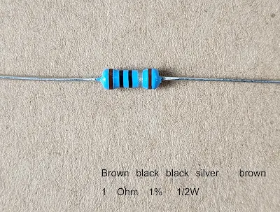
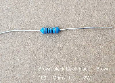
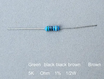
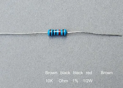
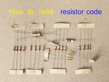
Color Code of resistor 1 Ohm 2 Ohm 10 Ohm 100 Ohm 2K 5K 10K and 100K
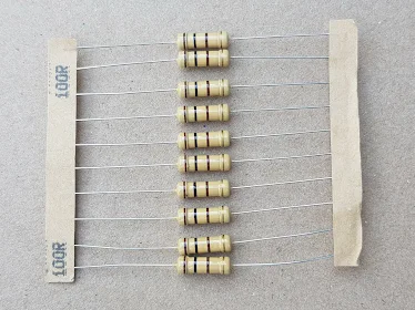
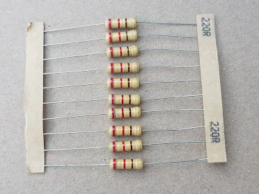
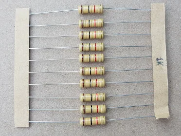
10 Ohm 100 Ohm 220 Ohm 1K 10K 100K colour Code resistor with value label
Resistor color code and its reading example set 3
Read resistor color code from real resistor
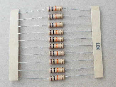
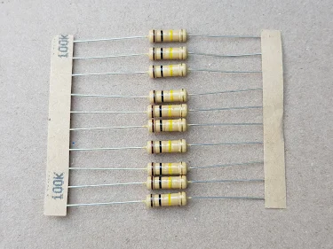
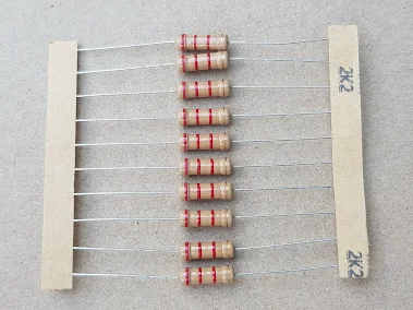
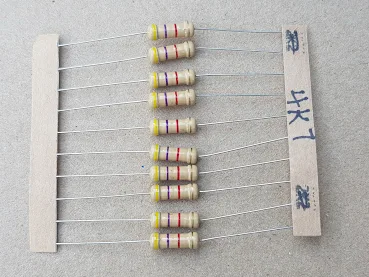
These are photo of resistor with label to present 10 Ohm 100 Ohm 220 Ohm 1K 10K 100K colour code resistor and more. For rechecking and confirm value of resistor. Many time we have question about lavue of resistor and we use a few method to find the resistor value such as test it by multimeter , seek manual and label on PCB , and compare color code with the good one.
Example of 4 bands resistor color code
1) 10 ohm resistor color code 0.5W ±5%
Brown black black gold
1 0 x1 ±5% = 10 Ohm ±5%
2) 100 ohm resistor color code 0.5W ±5%
Brown black brown gold
1 0 x10 ±5% = 100 Ohm ±5%
3) 220 ohm resistor color code 0.5W ±5%
Red red brown gold
2 2 x10 ±5% = 220 Ohm ±5%
4) 1K ohm resistor color code 0.5W ±5%
Brown black red gold
1 0 x100 ±5% = 1000 Ohm ±5% = 1K Ohm ±5%
5) 10K ohm resistor color code 0.5W ±5%
Brown black orange gold
1 0 x1000 ±5% = 10000 Ohm ±5% = 10K Ohm ±5%
6) 100K ohm resistor color code 0.5W ±5%
Brown black Yellow gold
1 0 x10000 ±5% = 100000 Ohm ±5% = 100K Ohm ±5%
7) 1M ohm resistor color code 0.5W ±5%
Brown black green gold
1 0 x100000 ±5% = 1000000 Ohm ±5% = 1M Ohm ±5%
8) 2.2K ohm resistor color code 0.5W ±5%
Red red red gold
2 2 x100 ±5% = 2200 Ohm ±5% = 2.2K Ohm ±5%
9) 4.7K ohm resistor color code 0.5W ±5%
Yellow violet red gold
4 7 x100 ±5% = 4700 Ohm ±5% = 4.7K Ohm ±5%
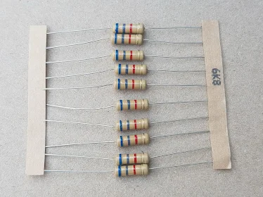
10) 6.8K ohm resistor color code 0.5W ±5%
Blue grey red gold
6 8 x100 ±5% = 6800 Ohm ±5% = 6.8K Ohm ±5%
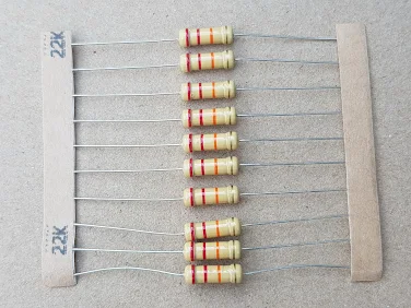
11) 22K ohm resistor color code 0.5W ±5%
Red red orange gold
2 2 x1000 ±5% = 22000 Ohm ±5% = 22K Ohm ±5%
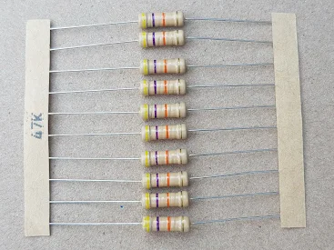
12) 47K ohm resistor color code 0.5W ±5%
Yellow violet orange gold
4 7 x1000 ±5% = 47000 Ohm ±5% = 47K Ohm ±5%
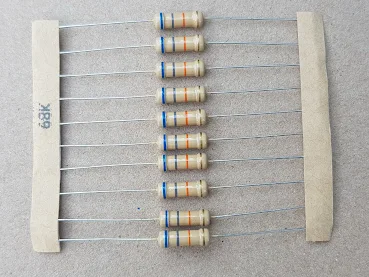
13) 68K ohm resistor color code 0.5W ±5%
Blue grey orange gold
6 8 x1000 ±5% = 68000 Ohm ±5% = 68K Ohm ±5%
14) 220K ohm resistor color code 0.5W ±5%
Red red yelllow gold
2 2 x10000 ±5% = 220000 Ohm ±5% = 220K Ohm ±5%
15) 470K ohm resistor color code 0.5W ±5%
Yellow violet yelllow gold
4 7 x10000 ±5% = 470000 Ohm ±5% = 470K Ohm ±5%
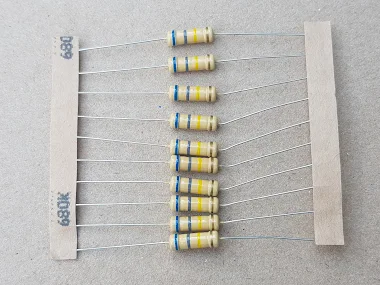
16) 680K ohm resistor color code 0.5W ±5%
Blue grey yelllow gold
6 8 x10000 ±5% = 680000 Ohm ±5% = 680K Ohm ±5%
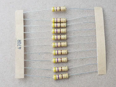
17) 470 ohm resistor color code 0.5W ±5%
Yellow violet brown gold
4 7 x10 ±5% = 470 Ohm ±5%
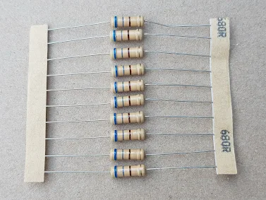
18) 680 ohm resistor color code 0.5W ±5%
Blue grey brown gold
6 8 x10 ±5% = 680 Ohm ±5%
How to test a transistor good or bad condition with hFE test
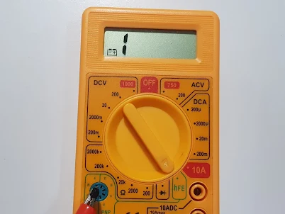
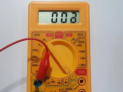
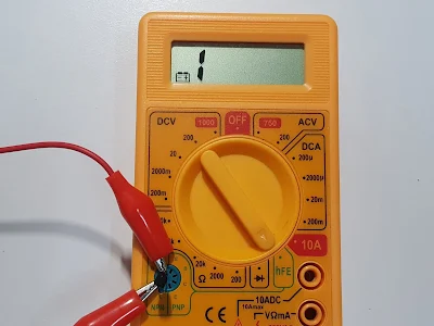
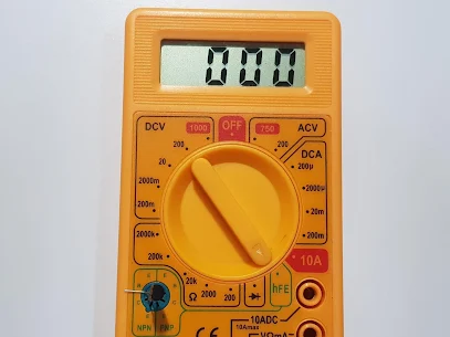
Test a transistor good or bad , hFE test
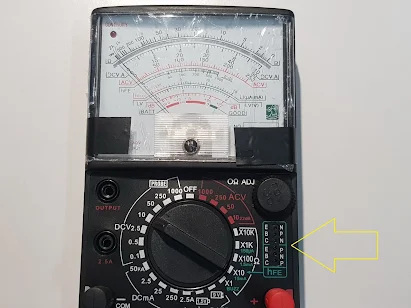
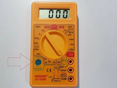
Transistor test socket
Step to check a transistor hFE.
1. Find a transistor terminal arrangement and DC current gain from its datasheet. For example transistor part number :
2N3904 is NPN type , terminal arrangement : E-B-C and hFE = 100(min)-300(max) .
2N3906 is PNP type , terminal arrangement : E-B-C and hFE = 100(min)-300(max).
2. Insert the right terminal to the right socket and transistor type. B terminal to B socket , C terminal to C socket and E terminal to E socket.
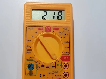
hFE test of 2N3906 PNP transistor , good transistor will display hFE
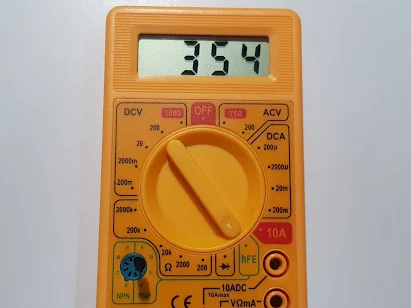
3. In case of bad transistor : shorted , opened will display as demonstration below.
C-E shored demonstration , bad transistor
Open E terminal demonstration , bad transistor
Read more of testing , list of article here .
Example test of Multifunction tester and How to use M tester TC1
How to use M tester TC1 Multifunction tester
Multifunction tester , non-rechargeable version and lower cost
The first necessary information before using , it need to know that socket arrangement and it name. Put the right terminal to the right socket function. Don't put too big terminal to socket ,in this case please use additional test leads. Additional test leads its purpose for testing big components and not easy to bend terminals. For capacitor testing always discharge capacitor before testing
Example testing of Multifunction tester
1. Zener Diode test. Insert a zener diode to KAA socket , Kathode terminal to K socket and Anode terminal to A socket. If is is a good Zener , display will show component name and the specification of zener diode as it should be.
2. Two terminal components testing. Such as resistor , capacitor , inductor , diode ect. Insert component to any 123 socket. In case of big terminals component use addition test leads. The display will show component detail what it should be. The bad component the display will show in different way.
2 terminal components insert to 1233 socket
