Multimeter use how to test IGBT and testing electronic components with multimeter

Multimeter  use  how  to   test   IGBT  using  Analog  Multimeter   and   Digital   Multimeter

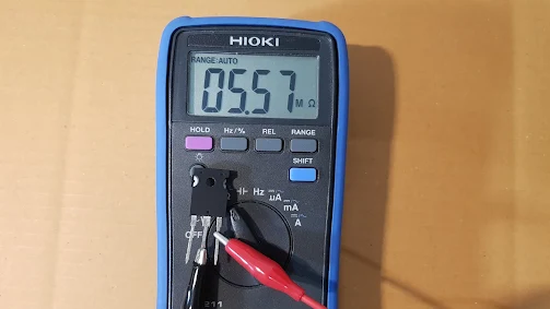
IGBT  TESTING     IGBT  has 3 legs  , namely  , Gate ,   collector  and  Emitter  , Its working principle  is  input voltage control output current.   we can use this basic bias to test whether it  is a   bad or good  IGBT. Important note analog Multimeter  use on this article it  is  a version that  black test lead  supply V+ and red  test lead supply V- , when  setting    to  resistance test function.


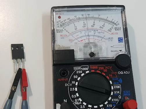
TEST   IGBT   Testing   electronic   device


TEST    IGBT   Check  IGBT


Test  multimeter   Testing  electronic  device
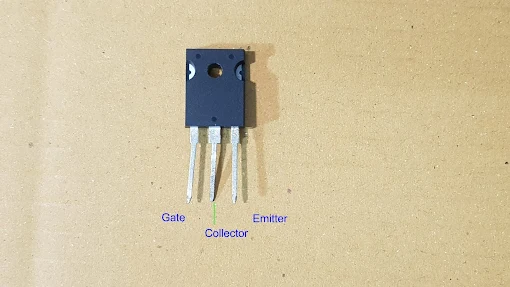
                   Sample  IGBT  has  Gate  Collector   and   Emitter ( pin No.  1 2 3 respectively )


Step to test  IGBT  ON / OFF TESTING
1.  Take  IGBT  part number  to find  leg function from datasheet.
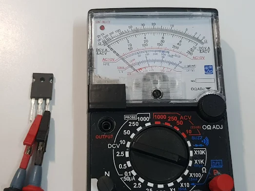
2.  Connect test leads with  IGBT  leg as photo above.
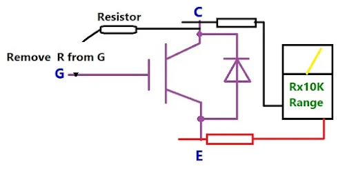
3.  Set analog multimeter to  Rx10K  as  this range it will  supply  9VDC  from internal battery.  9VDC is high enough  to  bias gate leg  so  IGBT is  working as  ON state.
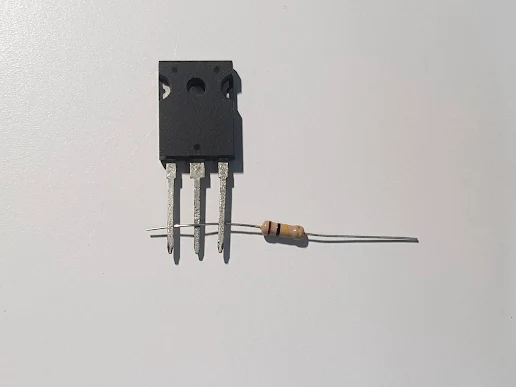
4. Use  resistor's  leg to temporarily  connect  between  G  leg and C leg ; the pointer's of multimeter move  forward  to  low resistance  as shown  on  photo.
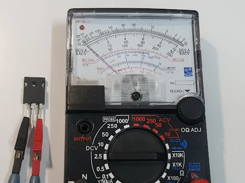
5. After removing resistor leg  the pointer 's of multimeter  hold
the same position  because   IGBT  is still working  as  ON  state , this is  for a  good  IGBT indication   but  the bad  IGBT  can not  hold  ON state  so  the  multimeter's   pointer   move backward  to   ∞  position after  removing resistor's leg.

Test IGBT with Multimeter BAD or Good Condition

Test    IGBT    with    Multimeter 

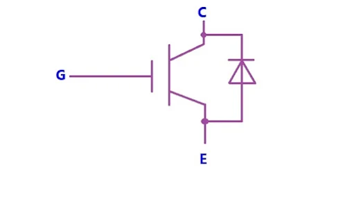
How  to  test  IGBT with  multimeter , it  will explain on  this article.   If  anyone  can  use  a  basic  multimeter and  know  how  to  test diode , it can easily test  IGBT  too.  Before  testing  notice  the IGBT terminals , It has  G ,  C and  E terminal.  G = Gate ,  C= Collector,  E = Emitter.   Some model  of   IGBT has internal diode connected  across  C and E terminal.  Hight current  and  big IGBT tend to  fail  as shorted and open condition so  before testing all process you may firstly check  shorted and open condition.


IGBT  Symbol

Test    IGBT   test  with   multimeter

 Discharge IGBT by shorting 3 terminal together.  This sample IGBT  has terminal arrangement  as   G   C   E  ( 1-2-3 respectively ).


Step  to  Test  IGBT   with  a   multimeter .

1.  Discharge IGBT by shorting 3 terminal together. Use resistor legs or other similar metal wire.  After discharge do not touch any its terminal and during the test process always hold at insulated area or black case.   Remove  IGBT  from circuit  before doing  any any  testing.

2.  Test  C and  E  terminals by using Rx1K   Ohm range.  Touch the test lead and read the measured value.   Switch the test lead and   read the measured value again.   Good  IGBT  will  display some resistance  1 time  and  ∞  1  time.  Shored  IGBT will point at 0 Ohm  2 time.  Open IGBT  will point at ∞    2   time.


Test    IGBT   with  multimeter
                    Good  IGBT  will   point  at  some resistance  1 time .


Test  IGBT   with multimeter
                 Good   IGBT  will   point   at   ∞   scale     1  time 


3.  Test  G and  C  terminals by using Rx10K   Ohm range.  Touch the test lead and read the measured value.   Switch the test lead and  read the measured value again.    Good IGBT  will  display  ∞   2   time.

4.  Test  G and  E  terminals by using Rx10K   Ohm range.  Touch the test lead and read the measured value.   Switch the test lead and read the measured value again.   Good  IGBT  will  display  ∞  2   time.


Test  multimeter    Test   IGBT

                     Test  G and  C   terminals   by using   Rx10K   Ohm range.


Test   IGBT   with multimeter

                     Test  G and  E   terminals by using   Rx10K   Ohm range.


All step  1 ,  2  ,  3 to 4 testing must    be good condition so the IGBT is good condition.  If any of  only 1 step is  fail so the IGBT is already bad.


Simple   method  to test IGBT  is   Gate  trig.

Discharge the IGBT by shorting 3 terminal together. During the test process do not touch any terminal and always hold  IGBT at  black case.    Connect the lest lead  as photo then use resistor to supply trig voltage from C terminal to trig G terminal.   Good IGBT will cause  pointer  of   multimeter  move  forward and point at some resistance.  then remove  the resistor ( trig voltage) ,  the IGBT still let current flow and the pointer still  point  at  the same position  when  trig  Gate.

Test   IGBT    with multimeter

                                         Connection  of   test  leads  to trig  Gate  of   IGBT


Test   IGBT

              After removing  trig voltage , the pointer still point  the same position  ( for good IGBT)


Read   more  ,   list   of   article  here .
Test SCR / THYRISTOR MODULE with multimeter

How    to   test    SCR   Module 

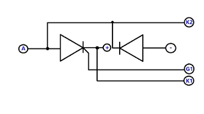
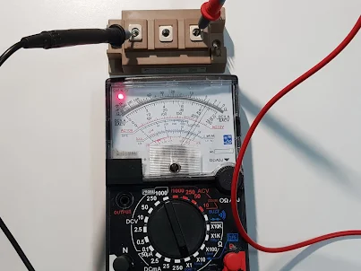
SCR   /   THYRISTOR   MODULE    is   a   power  electronic device which  is for  high current and high voltage application.  It  still  use  multimeter to test its condition : good or bad.   The step to check is almost the same as small  SCR  and same principle  , however , there is some difference in  detail  , for example we can not use multimeter to trig gate of  SCR because  it is a  power  electronic device.  There are many model  of  SCR module in  the market.  On  its name plate  there is  internal circuit diagram that is useful  to check  and  installation.


Test    SCR   THYRISTOR  MODULE   with   multimeter
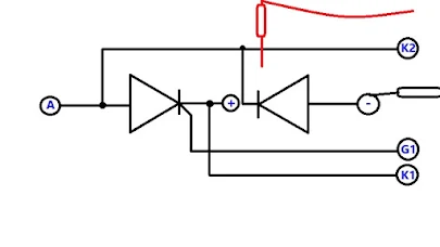
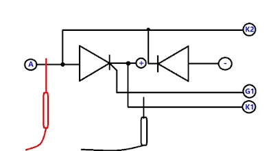
                      The example  SCR  module consist of   1 SCR and  1  Diode.


Step to check  SCR  /  THYRISTOR  MODULE   with   multimeter

1. Find the terminal and internal circuit diagram of  SCR  from its name plate or datasheet.
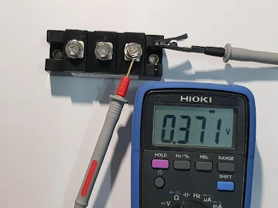
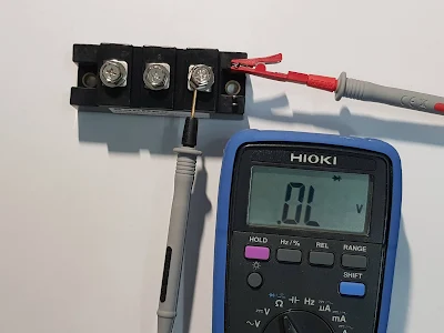
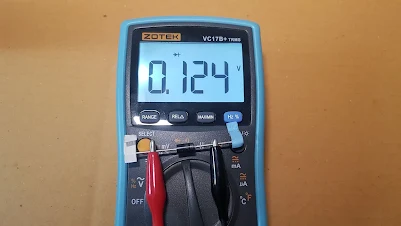
2. From the example SCR module  consist of  1 SCR and  1 Diode.   Check  diode  firstly   by using  Diode check  range  on digital multimeter.  The good diode will  present  forward voltage drop  0.3-0.7V ( forward bias) and  display  OL  1 time when reverse bias.  Shorted diode display 000V 2 time and  Open diode display OL  2  time.   If  diode is already bad , no need to do the next  step.


Test  SCR  module
                                         Check   diode   of   THYRISTOR  MODULE


Test   SCR  Module  Test   multimeter
         Forward bias to diode  , there is  0.371V forward voltage drop .  = good diode


Test   SCR

                             Reverse  bias to diode  ,  display    " OL "   =  good diode

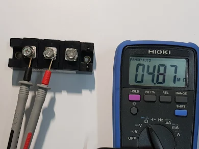
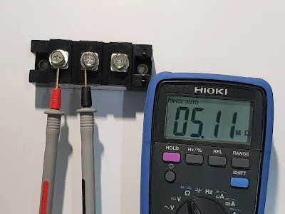
3.  Check     SCR   condition  ,  A  and  K1   terminal.  Set to Ohm meter range  , good  SCR will  display  very  high  resistance  as Mega Ohm.   Shorted SCR , multimeter display 0 Ohm  and   Open SCR , multimeter display  OL.

Test  SCR


Test  SCR   with  Multimeter
   Check   A  and  K1   terminal  of  SCR  ,  good SCR get very high resistance Mega Ohm.


Test    SCR     THYRISTOR  MODULE   with   multimeter
  Check   A  and  K1   terminal  of  SCR  ,  good SCR get very high resistance Mega Ohm.


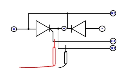
4.  Check     SCR   condition  ,  G1  and  K1   terminal.  Set  to Ohm   range  on digital multimeter , good  SCR will  display  low  resistance .   Shorted SCR , multimeter display 0 Ohm  and   Open SCR , multimeter display  OL.

Test    SCR     THYRISTOR  MODULE   with   multimeter

Test    SCR     THYRISTOR  MODULE   with   multimeter
           Check     G1  and  K1   terminal.   , good  SCR will  display  low  resistance .


Test    SCR     THYRISTOR  MODULE   with   multimeter
           Check     G1  and  K1   terminal.   , good  SCR will  display  low  resistance .


Analog  multimeter  can  check diode on SCR module  too  if  it is a good diode will point at  low resistance when forward biasing and  point at ∞  (Infinity) Ohm  when reverse biasing.   Check  G1  and  K1   terminal of  SCR module  , good  SCR will  display  low  resistance so it can check by  Rx1  Ohm  Range.   However , A  and  K1   terminal of  SCR   is 4-5 Mega Ohm resistance analog multimeter can not  display or present any pointer  movement   this  is  very high value , after try with the same module and same condition ,  it always point at  point at ∞  (Infinity) Ohm.


Read    more     of    testing    ,   list    of    article   here  . 
How to test IGBT Module with multimeter

 Test    IGBT   Module   with   multimeter

We  can  check  IGBT module condition :  good or bad with  analog  multimeter.  It is a basic testing with the most common tester.   Besides checking good or bad condition ,  we   check  to compare the measured  parameter  of   IGBT  from  different   supplier  as    maintenance  experience sometime we found IGBT is a  good condition when checking with multimeter  ,  but  when comparing  the measured  parameter  it has  some difference in detail.  Note   IGBT  module is a  power electronic devices  which is working at high current and high voltage ,  we  check  it  with a   multimeter that  is  a  low voltage testing ( analog multimeter 3VDC and 9VDC from Ohm range and  digital multimeter around  2.7V) sometime it found that it is a good IGBT if checking it with multimeter but  it fail when working  at high voltage and current.   However , checking it  with   multimeter  is  still  useful  and  necessary for repairing circuit.


How to to test  IGBT  Module  with  multimeter


How to to test  IGBT  Module  with  multimeter

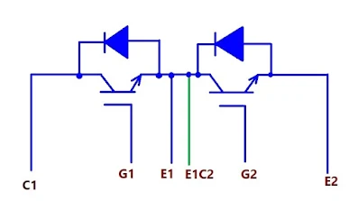
                                    Internal    circuit   diagram   of    example   IGBT


Look  at  the  body of IGBT there is  terminal Gate ( G) , Collector ( C ) and Emitter ( E). Some model there is  one IGBT inside the module and some model has  2 IGBT inside the module.


Step to  test  IGBT module with analog  Multimeter.

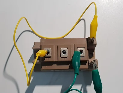
1.  Discharge  IGBT  by  shorting  3  terminal together ( G-C-E short).   The test IGBT must remove from circuit and there is no power present while checking.

2.  After discharging ,  do not touch any  metal terminal   and   hold at insulated case  if  need.


Test   IGBT  module
                                Discharge IGBT by shorting  3 terminal together


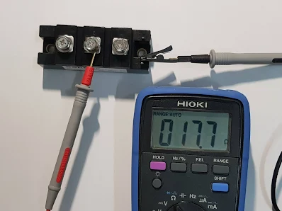
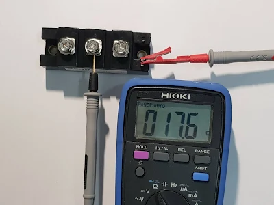
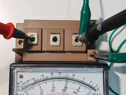
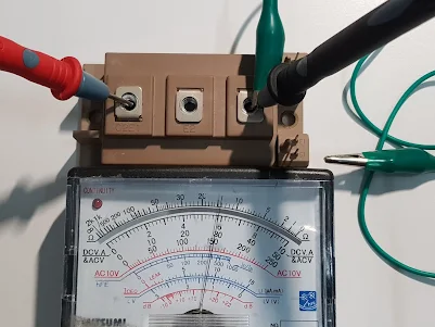
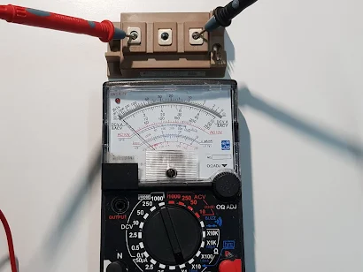
3.  Checking diode No. 1 at C1-E1 terminal  and  Diode No.2  at  C2-E2 terminal.  Set  range switch to  Rx1.  Good diode , the pointer will point at low resistance when forward biasing and the pointer will point at  ∞ Infinity scale when reverse biasing.   Shorted diode the pointer will point at  O Ohm and open diode   the  pointer  will  point  at   ∞ Infinity scale  2 time.


testing electronic components with multimeter
                    Forward bias to diode ,  the pointer will point  at  low resistance


Test   multimeter  Test   IGBT
                 Reverse  bias to diode ,  the pointer will point  at  ∞ Infinity scale  2 time.


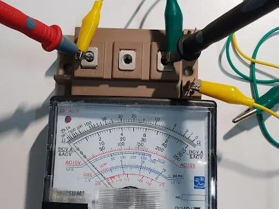
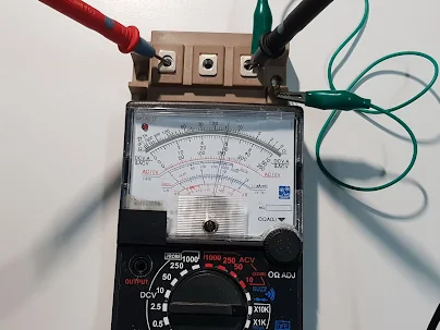
4. Checking Gate biasing  to  ON  and  OFF  the   IGBT.  Set the range switch to  Rx10K  as this range of  multimeter supply  9VDC from  the  test lead to provide  basic  bias  IGBT.  Good IGBT can bias to ON and OFF.  Bad  IGBT can not bias (fail) to ON and OFF.


Test   IGBT  with multimeter
        Connect the test lead with IGBT ,  terminal  C1  E1 and G1  as photo below.


test  IGBT  Module  with  multimeter

   Trig   G1  to turn on   the IGBT , connect the test lead with   terminal  C1  E1 and  G1  


test   IGBT  Module  with  multimeter
       Remove  trig voltage from G1 , the IGBT still let current flow and the pointer still   point at the same scale as   time  when  connecting voltage to  trig  G1.


test  IGBT  Module  with  multimeter
 Turn  OFF  IGBT  by  short  G1 to  E1 terminal , the pointer move backward  to  ∞  scale 


5.  Repeat process  step 4 to check  Gate biasing  to  ON  and  OFF   IGBT No.2  (  C2 , E2 , G2)


Note  this  is  a  basic and  low  voltage  testing.  It tend to be good condition  when IGBT working at high voltage at specific circuit  , but sometime we found  it fail  at high voltage test.  You need to test and compare measured  Ohm  value  of  IGBT    that  from difference supplier.


Read     more    of     testing    ,   list    of    article   here .


Multimeter use how to test DIODE by multimeter

HOW     TO    TEST    DIODE    by   digital   multimeter   and  Analog multimeter


Test  multimeter     Test    Diode


DIODE    TESTING

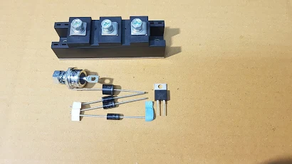
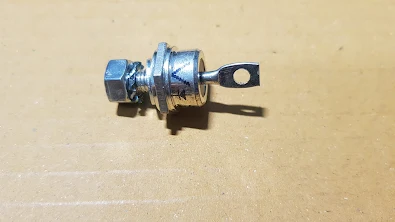
Diode   is  a  basic electronic device and it  has wide application  on   many  circuit such as  rectifying , switching ,  protection circuit  , polarity protection  etc. Before checking   it  need to know  a necessary information about diode.   Diode has many package below is some example. On its body  has  shown  diode symbol so that you  can  know its   terminal function   anode or cathode.

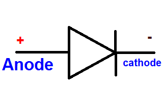
This   is  a   symbol  of  diode ,  Anode for  positive voltage ( + ) and  Cathode for negative voltage.   If   supplying  the right polarity voltage  to  the   diode  terminal  ... V+   to  anode and V-  to cathode   this  called  " Forward  Bias "    this case diode will let current flow.  If   supplying  reverse polarity to the  diode ..... V-  to  Anode terminal  and  +  to  Cathode terminal ,  this case diode will block current and  no current flow   this called reverse bias.   In case of  reverse bias there is only  leakage current  flow and  amount  as uA or  mA  for  Germanium Diode and  there is   not  any leakage current  for  Silicon Diode.

Test  Diode
                                Test    DIODE   with   multimeter  


test  DIODE


DIODE


Stud DIODE