Test IGBT Module with multimeter
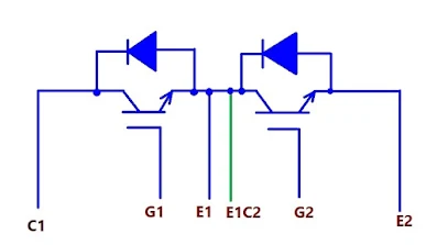
Internal circuit diagram of example IGBT
Look at the body of IGBT there is terminal Gate ( G) , Collector ( C ) and Emitter ( E). Some model there is one IGBT inside the module and some model has 2 IGBT inside the module.
Step to test IGBT module with analog Multimeter.
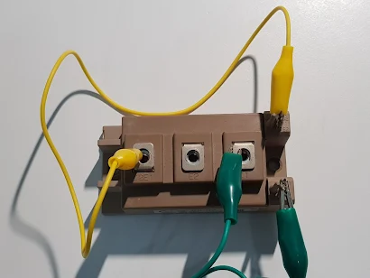
1. Discharge IGBT by shorting 3 terminal together ( G-C-E short). The test IGBT must remove from circuit and there is no power present while checking.
2. After discharging , do not touch any metal terminal and hold at insulated case if need.
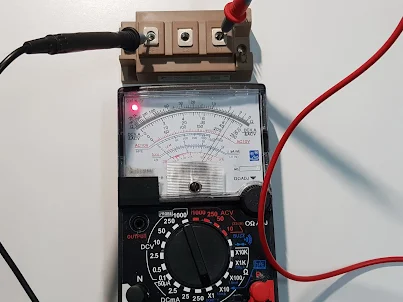
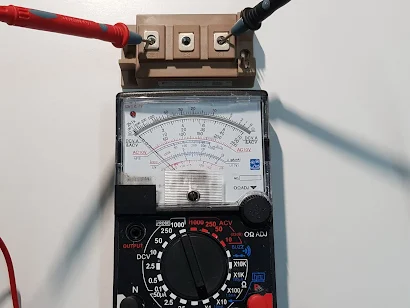
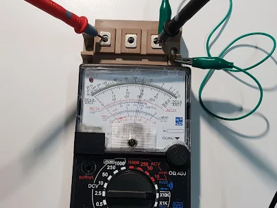
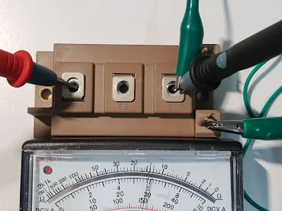
3. Checking diode No. 1 at C1-E1 terminal and Diode No.2 at C2-E2 terminal. Set range switch to Rx1. Good diode , the pointer will point at low resistance when forward biasing and the pointer will point at ∞ Infinity scale when reverse biasing. Shorted diode the pointer will point at O Ohm and open diode the pointer will point at ∞ Infinity scale 2 time.
Reverse bias to diode , the pointer will point at ∞ Infinity scale 2 time.
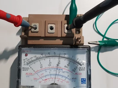
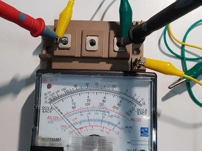
4. Checking Gate biasing to ON and OFF the IGBT. Set the range switch to Rx10K as this range of multimeter supply 9VDC from the test lead to provide basic bias IGBT. Good IGBT can bias to ON and OFF. Bad IGBT can not bias (fail) to ON and OFF.
Remove trig voltage from G1 , the IGBT still let current flow and the pointer still point at the same scale as time when connecting voltage to trig G1.
Turn OFF IGBT by short G1 to E1 terminal , the pointer move backward to ∞ scale
5. Repeat process step 4 to check Gate biasing to ON and OFF IGBT No.2 ( C2 , E2 , G2)
Note this is a basic and low voltage testing. It tend to be good condition when IGBT working at high voltage at specific circuit , but sometime we found it fail at high voltage test. You need to test and compare measured Ohm value of IGBT that from difference supplier.

