HOW TO TEST BRIDGE RECTIFIER DIODE
HOW TO TEST BRIDGE RECTIFIER DIODE
HOW TO TEST BRIDGE RECTIFIER DIODE
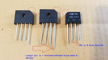
Full bridge rectifier diode consists of 4 diode inside the package. It is a common part of power supply. Internal wiring for 4 diodes shown as below. Although there are many package of Full bridge rectifier diode , it has the same internal wiring diagram and 4 terminals , namely ; + , - AC and AC.
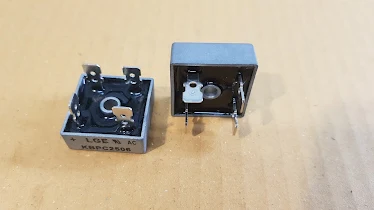
The + terminal has longer lead than the others and there is cut marking at the corner . The sip package AC and AC leads located at the inner. KBPC package indicate only 2 terminal name that is + and AC , the others you have to find ... - terminal is diagonal to the + terminal and the rest AC terminal is diagonal to the first AC terminal too.
Leads arrangement of BRIDGE RECTIFIER DIODE
SIP package BRIDGE RECTIFIER DIODE
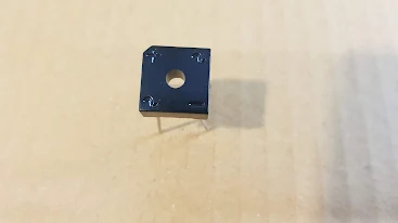
KBPC package has quick connect terminals.
Shown terminal arrangement for KBPC package. AC terminal is diagonal to AC terminal , also , - terminal is diagonal to + terminal.
BRIDGE RECTIFIER DIODE TERMINAL FUNCTION
Step to check bridge rectifier diode.
Before checking. study this internal wiring of 4 diodes first. D1 and D3 arrow head has the same direction. D2 and D4 arrow head has the same direction too. When supplying forward bias to D1 and D3 there is some voltage drop. 1 diode has around 0.5-0.8V voltage drop so if 2 diodes ( D1 and D3 ) voltage drop will be as 0.5V x 2 = 1V approximately , or some case 0.8Vx2 = 1.6V . For D2 and D4 likewise.
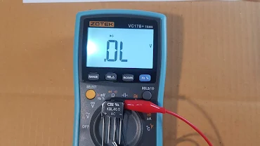
1. Turn rotary knob of multimeter to Diode Function.
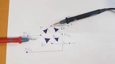
2. Connect the test leads as photo. If Diode is good , multimeter will display voltage drop diode around 1V. 1V is a voltage drop across 2 Diode ( 0.5Vx2). If there is 1 of any didoe short , the meter will display around 0.5V. If there is any bad diode found as short or open , no need to do the next checking.
Connect test lead to + and - terminal.
Set meter to diode test function.
Set meter to diode test function.
Connect test lead to + and - terminal.
There is voltage drop across diode ( 0.8-1V) = good diode
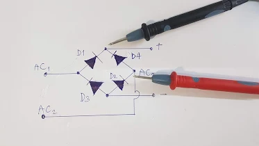
3. D3 testing. connect test leads as photo below to check the individual diode , D3.
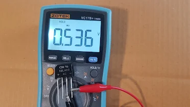
The good diode will get around 0.5V. Short diode will display 0.002 and open diode will display " OL"
In case of diode is good , it will display some voltage drop on example is 0.536V
In case of bad diode (short) , it will display very low voltage drop on example is 0.002V
In case of bad diode (open) , it will display "OL"
4. D2 testing. check the individual diode , D2. Connect test lead as photo below.
The good diode will has voltage drop around 0.5V.
For bad diode (short and open) already described on above photo.
5. D1 testing. check the individual diode , D1. Connect test lead as photo below.
The good diode will has voltage drop around 0.5V.
For bad diode (short and open) already described on above photo.
5. D4 testing. check the individual diode , D4. Connect test lead as photo below.
The good diode will has voltage drop around 0.5V.
For bad diode (short and open) already described on above photo.
In addition when you measure AC1 and AC2 terminal , it must not be as short connection. Terminal + and - it must not be as short connection too. The above checking is off -board checking. If you want to do on board checking and use voltmeter function to check the output of full bridge rectifier diode by using this equation.
Vdc = 1.41 x Vac if there is capacitor filter and resistor load.
Vdc = 0.9 x Vac if there is resistor load only.
8 Important Testing electronic device on this blog .
Testing electronic device IGBT testing SCR testing Triac Testing Check mosfet and more
Read on this page.
Read more .... all of testing , list of the article here .

