HOW TO TEST DIODE by digital multimeter and Analog multimeter
DIODE TESTING
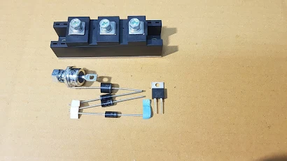
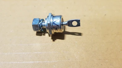
Diode is a basic electronic device and it has wide application on many circuit such as rectifying , switching , protection circuit , polarity protection etc. Before checking it need to know a necessary information about diode. Diode has many package below is some example. On its body has shown diode symbol so that you can know its terminal function anode or cathode.
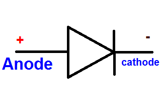
This is a symbol of diode , Anode for positive voltage ( + ) and Cathode for negative voltage. If supplying the right polarity voltage to the diode terminal ... V+ to anode and V- to cathode this called " Forward Bias " this case diode will let current flow. If supplying reverse polarity to the diode ..... V- to Anode terminal and + to Cathode terminal , this case diode will block current and no current flow this called reverse bias. In case of reverse bias there is only leakage current flow and amount as uA or mA for Germanium Diode and there is not any leakage current for Silicon Diode.
Test DIODE with multimeter
Module package it use for high current and high voltage diode. Inside the module may consist of 1 or 2 or 3 or 4 diode , it depends on diode part number. On module , there is diode symbol and internal wiring connection for technician to install and test it.
Step to check Diode .
This testing is a off-board testing.
1. Turn rotary switch of multimeter to Diode test Function as photo. On display will show diode symbol and multimeter knob will direct to Diode symbol too.
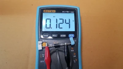
2. Connect red test lead to anode and black test lead to cathode terminal ( forward bias ) . Note that the white band is Cathode terminal . you will see voltage drop across diode 0.5-0.8V for Silicon Diode and 0.1V - 0.3V for Germanium diode. Switching the test leads ; red to Cathode pin and black to Anode pin , the good diode will display as " OL " ( Over Limit )
Good diode there is voltage drop across diode = 0.1V - 0.3V for Germanium diode (forward bias)
If it is a bad diode ( open ) , it will show " OL " 2 time for both the first measurement ( forward bias) and the second measurement ( reverse bias ) as photo below.
If it is a bad diode ( shorted ) , it will show " very low voltage drop " 2 time for both the first measurement ( forward bias) and the second measurement ( reverse bias ) as photo below.
Before checking it need to know the real polarity of voltage from the test leads. The color of test lead may cause confusion to begin learner. Red is for positive (+) that correct , but , when we set the knob of analog multimeter to resistance test function the red test lead connect to negative polarity of internal battery so the red test lead supply V-. The black test lead connect to the positive polarity of internal battery so the black test lead supply V+. Summary red test lead = V - and black test lead = V+ . See diagram below to simplify.
1. Turn rotary switch of analog multimeter to Rx1 range resistor test function for medium and big diode testing , Rx10 range for small diode testing.
2. Forward bias checking , connect the red test lead to kathode terminal ( note kathode terminal has white band ) and the black test lead to anode terminal . The good diode will display low resistance and LED on the multimeter light as shown photo below
3. Reverse bias checking .. connect the red test lead to Anode terminal and black test lead to kathode terminal . The good diode will display very very high resistance the pointer point at ∞ infinity as shown on photo below.
4. If it is a bad diode ( open ) , it has very high resistance the pointer point at ∞ scale (infinity) 2 time ....for the first measurement ( forward bias checking ) and the second measurement ( reverse bias checking )
5. If it is a bad diode (shorted ) , it will show " very low resistance nearly 0 ohm 2 time for the first measurement ( forward bias checking ) and the second measurement ( reverse Bias checking ) shown as photo below.
8 Important Testing electronic device on this blog .
Testing electronic device IGBT testing SCR testing Triac Testing Check mosfet and more
Read on this page.


