Resistor color code 5 band 330 Ohm 27 Ohm 33 Ohm 150 Ohm 270 Ohm and more example

 Resistor   color   code   and   its  reading  example  set 2
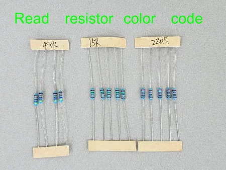
Read   resistor  color  code
                           Read   resistor  color  code  from   R  label


These are  example  of   resistor color code 5 band ,  330 Ohm  27 Ohm  33 Ohm 150  Ohm  270 Ohm and more.  For   reference   and   double check the value of resistor including learning  how to read resistor color code 5 band  from real resistor photo.   It has label from factory to ensure the right value.


1)     27   Ohm resistor color code   metal  film    1W   ± 1%.
   Red   violet    black   gold       brown   
   2         7          0         x 0.1     ± 1%        =   27 Ohm  ± 1% 

27  Ohm  resistor   color  code


2)     33   Ohm resistor color code   metal  film    1W   ± 1%.

   Oragne   orange    black   gold       brown   

    3               3          0         x 0.1      ± 1%        =   33    Ohm  ± 1% 

33   Ohm  resistor   color code


3)     39   Ohm resistor color code   metal  film    1W   ± 1%.

   Oragne    white    black   gold       brown   

    3               9          0         x 0.1      ± 1%        =   39    Ohm  ± 1% 

Resistor  39   Ohm  color code


4)     56   Ohm resistor color code   metal  film    1W   ± 1%.

   Green       blue    black    gold       brown   

    5               6          0         x 0.1      ± 1%        =   56    Ohm  ± 1% 

Resistor   56   Ohm


5)     75   Ohm resistor color code   metal  film    1W   ± 1%.

      Violet    green    black    gold       brown   

      7             5          0          x 0.1      ± 1%        =   75    Ohm  ± 1% 

Test  multimeter  read resistor color code


6)     150   Ohm resistor color code   metal  film    1W   ± 1%.

      Brown    green    black    black       brown   

       1             5          0           x 1       ± 1%        =   150    Ohm  ± 1% 

Resistor   150    Ohm


7)     200   Ohm resistor color code   metal  film    1W   ± 1%.

       Red         black    black    black       brown   

       2             0           0           x 1          ± 1%        =   200    Ohm  ± 1% 

read resistor color code


8)     270   Ohm resistor color code   metal  film    1W   ± 1%.

       Red        violet    black    black       brown   

       2             7           0           x 1          ± 1%        =   270    Ohm  ± 1% 

Resistor  270   Ohm


9)    330   Ohm resistor color code   metal  film    1W   ± 1%.

       Oragne    Orange   black    black       brown   

        3             3             0           x 1          ± 1%        =   330    Ohm  ± 1% 

Test  multimeter  Resistor  330   Ohm


10)    390   Ohm resistor color code   metal  film    1W   ± 1%.

       Oragne    white     black     black       brown   

        3             9             0           x 1          ± 1%        =   390    Ohm  ± 1% 

Resistor  390   Ohm


11)    470   Ohm resistor color code   metal  film    1W   ± 1%.

       Yellow     violet     black     black       brown   

        4              7             0           x 1          ± 1%        =   470    Ohm  ± 1% 

read resistor color code


12)    560   Ohm resistor color code   metal  film    1W   ± 1%.

       Green     blue         black     black       brown   

        5              6             0           x 1          ± 1%        =   560    Ohm  ± 1% 

Test  multimeter  Resistor 560   Ohm


13)    750   Ohm resistor color code   metal  film    1W   ± 1%.

       Violet      green         black     black       brown   

        7              5              0            x 1          ± 1%        =   750    Ohm   ± 1% 

Resistor  750   Ohm


14)    2K   Ohm resistor color code   metal  film    0.5W   ± 1%.

     Red       black     black    brown     brown   

     2            0           0           x 10        ± 1%     =   2000  Ohm  ± 1%   = 2K Ohm  ± 1% 

Resistor   2K   Ohm


15)    3.6K   Ohm resistor color code   metal  film    0.5W   ± 1%.

     Orange     blue     black    brown     brown   

     3               6           0           x 10        ± 1%     =   3600 Ohm  ± 1%   = 3.6K Ohm  ± 1% 

Resistor  3.6K   Ohm


16)    47K   Ohm resistor color code   metal  film    0.5W   ± 1%.

    Yellow    violet     black    red        brown   

     4             7            0         x 100     ± 1%     =   47000 Ohm  ± 1%   = 47K Ohm  ± 1% 

Resistor  47K   Ohm


17)    1.5M   Ohm  resistor color code   metal  film    0.5W   ± 1%.

    Brown    green    black   green         brown   

     1             5          0        x 100000     ± 1%     =  15000000 Ohm  ± 1%   = 1.5M  Ohm  ± 1% 

Resistor  1.5M   Ohm


18)    2.2M   Ohm  resistor color code   metal  film    0.5W   ± 1%.

    Red    red    black   green          brown   

     2       2         0        x 100000     ± 1%     =  22000000 Ohm  ± 1%   = 2.2M  Ohm  ± 1% 

Resistor 2.2M   Ohm


19 )    10M   Ohm  resistor color code   metal  film    0.5W   ± 1%.

    Brown   black   black   green          brown   

     1           0          0        x 100000     ± 1%     =  10000000 Ohm  ± 1%   = 10M  Ohm  ± 1% 

Resistor 10M   Ohm


how to read resistor values


Topics    to   read    more.

1 Ohm 10 Ohm 100 Ohm 1000 Ohm 1K 10K 47K resistor color code and more example

  Resistor   color   code   and   its  reading  example  set 1


how to read resistor


These  are  resistor  color code   of   1 Ohm   2 Ohm  10 Ohm  100 Ohm  1000 Ohm  1K Ohm  10K Ohm  100K    47K Ohm    1M  and more.   Some resistor on  PCB  damaged  and  we need the right information to compare and find the replacement.   You can use this photo to double check value of   the damage  resistor ,  the photo is big and with label for reference.


1)     1  Ohm resistor color code   metal  film    1W   ± 1%.
brown   black   black  silver   brown   
   1        0          0        x 0.01    ± 1%    =   1 Ohm  ± 1% 


1  Ohm  resistor  1R   color code


2)     2  Ohm resistor color code   metal  film    1W   ± 1%.

   Red   black   black   silver    brown   

   2        0          0        x 0.01    ± 1%     =     2 Ohm  ± 1% 

2  Ohm   2R    resistor  color  code


3)     10  Ohm resistor color code   metal  film    1W   ± 1%.

   Brown   black   black   gold    brown   

   1           0          0         x 0.1    ± 1%     =     10 Ohm  ± 1% 

10  Ohm  10R  resistor color  code


4)     100  Ohm resistor color code   metal  film    1W   ± 1%.

   Brown   black   black    black    brown   

   1            0          0          x 1       ± 1%                =     100   Ohm  ± 1% 

100  Ohm   resistor  color  code


5)     1K  Ohm resistor color code  ,  1K or  1000 Ohm   metal  film 0.5W     ± 1%.

   Brown   black   black    blown    brown   

   1            0          0          x 10       ± 1%                =     1000   Ohm  ± 1%   =  1K Ohm   ± 1% 

1K  Ohm resistor color code


6)     10K  Ohm resistor color code  ,    metal  film   0.5W     ± 1%.

   Brown   black   black    red    brown   

   1            0          0          x 100       ± 1%                =     10000   Ohm  ± 1%    =  10K Ohm   ± 1% 

10K  Ohm resistor color code


7)     100K  Ohm resistor color code  ,    metal  film   0.5W     ± 1%.

   Brown   black   black    orange     brown   

   1            0          0          x 1000       ± 1%           =    100000   Ohm  ± 1%    =  100K Ohm   ± 1% 

read resistor color code


8)     47K  Ohm resistor color code  ,    metal  film   0.5W     ± 1%.

    Yellow   violet    black    red       brown   

      4            7         0         x 100     ± 1%           =    47000   Ohm  ± 1%    =  47K Ohm   ± 1% 


47K  Ohm resistor

9)     1M  Ohm resistor color code  ,    metal  film   0.5W     ± 1%.

      Brown   black    black    yellow      brown   

      1            0          0         x 10000      ± 1%        =  1000000   Ohm  ± 1%    =   1M  Ohm   ± 1% 

1M   Ohm resistor


10)     0.1  Ohm resistor color code  ,   metal  film   1W     ± 1%.

   Black   brown   black    silver        brown   

    0            1          0          x 0.01       ± 1%                =    0.1   Ohm  ± 1%   

0.1  Ohm resistor


11)     0.5  Ohm resistor color code  ,   metal  film   1W     ± 1%.

   Black     green    black    silver        brown   

    0             5           0          x 0.01       ± 1%                =    0.5   Ohm  ± 1%   

Resistor  0.5  Ohm


12)     0.33  Ohm resistor color code  ,   metal  film   1W     ± 1%.

   Black      orange    orange   silver         brown   

    0             3            3             x 0.01       ± 1%                =    0.33   Ohm  ± 1%   

0.33  Ohm resistor


13)     2.7  Ohm resistor color code  ,   metal  film   1W     ± 1%.

   Red        violet      black       silver         brown   

    2             7            0             x 0.01       ± 1%                =    2.7   Ohm  ± 1%  

2.7  Ohm resistor


14)    3.3  Ohm resistor color code  ,   metal  film   1W     ± 1%.

   Orange    orange      black       silver         brown   

    3              3               0             x 0.01       ± 1%                =   3.3   Ohm  ± 1%  

read resistor color code


15)    3.9  Ohm resistor color code  ,   metal  film   1W     ± 1%.

   Orange    white      black       silver         brown   

    3              9               0             x 0.01       ± 1%                =   3.9   Ohm  ± 1%  

3.9  Ohm resistor


16)    4.7   Ohm  resistor color  code  ,   metal   film   1W     ± 1%.

   Yellow    violet      black       silver         brown   

    4              7               0             x 0.01       ± 1%                =   4.7   Ohm  ± 1%  

read resistor color code


17)    5.6  Ohm resistor color code  ,   metal  film   1W     ± 1%.

   Green      blue      black       silver         brown   

    5              6               0        x 0.01        ± 1%                =   5.6   Ohm  ± 1%  

Resistor  5.6  Ohm


18)    7.5  Ohm resistor color code  ,   metal  film   1W     ± 1%.

    Violet      green      black       silver         brown   

     7              5            0        x 0.01        ± 1%                =   5.6   Ohm  ± 1% 

7.5  Ohm resistor


19)    15  Ohm resistor color code  ,   metal  film   1W     ± 1%.

    Brown     green      black      gold         brown   

     1              5            0            x 0.1        ± 1%                =   15   Ohm  ± 1% 

Resistor  15   Ohm


20)    20  Ohm resistor color code  ,   metal  film   1W     ± 1%.

     Red       black      black      gold         brown   

     2              0            0           x 0.1        ± 1%                =   20   Ohm  ± 1% 

20  Ohm resistor

Read     more   topics     of      testing   ,   from   here.


Multimeter use how to test SCR electronic components testing

Multimeter   use   how   to   test     SCR   Digital multimeter or Analog Multimeter

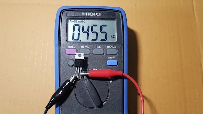
SCR   TESTING    SCR  has  3 legs , namely ,  Anode  Cathode  and Gate ,  we can use both Digital multimeter and  Analog Multimeter  to test SCR.   This article will present  the step to test.  The sample SCR to test on this article has pin function  K   A   G   ( terminal 1  2  3  respectively ) , the  SCR  part number is   TYN610.


วัดเอสซีอาร์  SCR   test  SCR   check  SCR

                                  HOW  TO  TEST    SCR

SCR


SCR

                                Sample  SCR   has  K  A  G  ( pin 1 2 3 respectively )


Step  to  test  SCR with   Digital multimeter.
1. Take part number to find leg function from datasheet.
2. Set digital multimeter to  resistance test function.
3. Connect test lead to  A and  K leg.
4. Test A and K leg  then switch the test leads   and   do   testing  again.

Multimeter use how to test TRIAC testing electronic components with multimeter

Multimeter    use   how   to   test    TRIAC      with   Digital  multimeter   Analog  multimeter

TRIAC  TESTING   Triac  has  3 legs  ,     T1   T2  G  and  some datasheet  named as   A1  A2  G and some datasheet named as   MT1  MT2  G.   You can use analog multimeter or  digital multimeter to test   good  Triac or bad Triac.  This   article will   explain   the step  to  test.


testing electronic components with  multimeter
                                HOW TO  TEST  TRIAC

TRIAC

Step to test  Triac with  Digital multimeter.
1. Take  triac part number to check with datasheet and find pin function.
2. Set digital multimeter to resistanc test function.
3. Test T1 and  T2 leg  then switch test leads and  do testing  again.

Multimeter use how to test MOSFET

How   to   test    MOSFET  with   multimeter

Multimeter   use   how   to   test    MOSFET  with  Digital  Multimeter   and   Analog    Multimeter 

MOSFET  TESTING    Mosfet working principle  is  input voltage control output current  , we can use  basic bias to test whether it is a  bad or good mosfet .  Mosfet has  Gate  Drain and source legs , take  part number  to find  leg function from datasheet then connect test leads as photo. Note  analog  multimeter on this testing  when set to  resistor  test function or Ohmmeter  , the black test  lead supply  V+  and  the red test lead supply V-  ; the reason is  the black test  lead is connected with positive polarity of internal battery and the red test lead is  connected with negative  polarity of internal battery. If you are unsure about polarity of  your multimeter test leads , you can check it with  multimer manual  or   ask   the multimeter  expert.


test    MOSFET   with   Multimeter
HOW TO  TEST   MOSFET 
TEST   MOSFET  with  multimetro  मल्टीमीटर
Connection diagram   to  test  MOSFET  with  Analog Multimeter.


Step to  check MOSFET  with  Analog Multimeter.

1.  Set analog multimeter to  Rx10K  as  this range the multimeter  will  supply 9VDC  from internal battery.  9VDC is  high enough  to bias gate leg so mosfet is working as  ON state.
2. Discharge  mosfet   by shorting  or connecting  3 leg  together  by  using  resistor's leg.   then do not  touch   the  legs.
3.  Connect test leads with mosfet leg as photo above
4. Use  resistor's  leg to temporarily  connect  between  G  leg and  D  leg ; the  pointer  of multimeter move  to  indicate  some  resistance  on ohm's   scale   as  photo.
5. After removing resistor's   leg  from mosfet's leg  the  pointer can  hold the same  position.

Test a zener diode with Digital multimeter Analog multimeter and multifunction tester.

Test    a    zener   diode   with    multimeter

Zener   diode   is  a   one  kind  of   diode   but   it   is  different from basic diode  in detail  and  application.   Here  it   will  focus  only   testing   a   zener   diode   with   multimeter.  Test example will present  for   digital   multimeter , analog  multimeter  , including   multifunction   tester.  You can compare  the  testing  which  use different  tester.


Test   Zener  Diode
                                 
                                The  black  stripe  indicate  Kathode  terminal


Step to test   a  zener   diode   with   multifunction   tester.

1.  Insert the Anode terminal to A socket and  Kathode  terminal  to   K socket.

2.  Press the button to start the test process and the tester will display zener diode voltage.  Multifunction   tester  TC1  can  detect  zener  voltage  range   0.01-30V


Test  Zener  Diode


Test   Zener  Diode


Step  to  test   a   zener   diode   with   digital   multimeter.

1.  Set the  range switch to diode test  , this range multimeter will supply  2.8VDC from test  lead. Test current will flow through a   zener  diode.

2. Forward bias to a zener diode , good  zener  diode will display some voltage drop across it which is as same as  basic diode test.

วัดซีเนอร์ไดโอด   Test  Zener  Diode
Forward bias , black test lead to Kathode and the red test lead to Anode , For a good zener diode ,  meter will display voltage drop across zener diode which is  as  same as basic diode test.


Test   Zener  Diode
Forward bias , black test lead to Kathode and the red test lead to Anode , For a good zener diode ,  meter will display voltage drop across zener diode which is as same as basic diode test.

3.  Reverse  bias to a   zener diode , a  good  zener  diode will display 2 case it depend on zener diode voltage.  It will display OL  if  zener voltage above 2.8V (  2.8V  is  test voltage  from multimeter).

and it will display the measured  zener voltage  if  a    zener  voltage  is lower than 2.8V.


Test   Zener  Diode
   Reverse  bias to a   zener diode , a good zener diode will display OL (zener voltage above 2.8V)


วัดซีเนอร์ไดโอด  Zener  Diode  Test
   
Reverse  bias to zener diode , a good zener diode will display measured  zener voltage  if a  zener voltage is lower than  2.8V.

4. Bad zener diode  ,  a  shorted  zener diode meter  will display 000V for forward biasing and reverse biasing.

5.  Bad zener diode  ,  an  open zener diode meter will display OL  for forward biasing and reverse biasing.


Step  to  test   a   zener   diode   with  analog  multimeter.

Analog   multimeter will supply 3VDC from the test lead when  setting  range to  Rx1 , Rx10 , Rx100, Rx1K . The polarity of  test  leads  , the red test lead   is   negative   and  the black test lead is positive (+3VDC)  , why was  this ,  it's because internal  AA  battery connection with the test leads.

1. Turn   the range switch  to  Rx10 for small zener diode.

2.  Forward  bias to a  zener  diode ;  the red test lead to Kathode terminal and the black test lead to Anode terminal. A good zener diode will present some voltage drop across it which is as same as basic diode test.


Test   Zener    Diode
   Forward  bias to a  zener  diode , red test lead to kathode and black test lead to anode.


Check  Zener  Diode
   Forward  bias to a  zener  diode , red test lead to kathode and black test lead to anode.


3.  Reverse  bias to a  zener  diode ;  the red test lead  to Anode  terminal and the black test lead to Kathode   terminal. A good zener diode will present 2 case it depend  on   a   zener  diode voltage.

Test  Zener  Diode
Reverse  bias to a  zener  diode ;  the red test lead to Anode  terminal and the black test lead to Kathode
A good zener diode , the pointer point at  ∞ Ohm.


วัดซีเนอร์ไดโอด  Test  Zener  Diode
Reverse  bias to a  zener  diode ;  the red test lead to Anode  terminal and the black test lead to Kathode
A good zener diode , the pointer  indicate measured  zener  voltage , in case of  zener  voltage is lower than  3VDC  ( 3VDC is  test  voltage from the test leads)


4. Bad zener diode  ,  a  shorted  zener diode , the pointer will  always point at 0 Ohm.  It is still point at  0 Ohm  when  switching  test   leads.

5.  Bad zener diode  ,  an  open zener diode  , the pointer will  always  point at  ∞  Ohm. It is still point ∞  Ohm   when  switching  test leads.


                          A  shorted  zener diode , the pointer will  always  point  at 0 Ohm.

Test  Zener  Diode

                       Open zener diode  , the pointer will  always  point at  ∞  Ohm


8    Important     Testing    electronic    device   on    this   blog . 
Testing  electronic device  IGBT testing SCR testing Triac Testing Check mosfet and more
Read   on   this   page.

Read    more ....    all    of   testing   ,   list    of    the    article   here .

30 testing of electronic devices